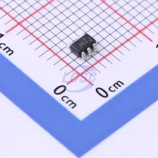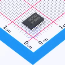

Nexperia
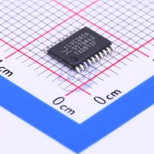
74LVC245APW,118Schmitt trigger 1.2V~3.6V 8 1 2.9ns@3.3V,50pF TSSOP-20 Buffers, Drivers, Receivers, Transceivers RoHS
From
₹28.71
2,48,995 in stock

1.65V~3.6V 8 7.4ns@3.3V SSOP-24-150mil Buffers, Drivers, Receivers, Transceivers RoHS
OCTAL BUS TRANSCEIVERS AND REGISTERS WITH 3-STATE OUTPUTS
Every Order Guarantee
100% Authentic · 30-Day Return or Replacement · policy
10 in stock
#C2675933
Stock & price checked 19 h ago
| Quantity | Unit price | Pack price |
|---|---|---|
| 1+ | ₹267.78 | ₹267.78 |
| 10+ | ₹260.91 | ₹2,609.10 |
| 30+ | ₹256.41 | ₹7,692.30 |
| 100+ | ₹251.91 | ₹25,191.00 |
1 × ₹267.78
₹267.78
excl. GST
₹315.98 incl. 18% GST
SN74LVC646ADBR
₹267.78 for 1 + GST
The SN54LVC646A octal bus transceivers and registers are designed for 2.7-V to 3.6-V VCC operation, and the SN74LVC646A octal bus transceivers and registers are designed for 1.65-V to 3.6-V VCC operation. These devices consist of bus-transceiver circuits, D-type flip-flops, and control circuitry arranged for multiplexing data from the input buses or internal registers. Data on the A bus or B bus is latched into the registers on the low-to-high transition of the respective clock (CLKAB or CLKBA) input. The output enable (OE) and direction control (DIR) inputs control the transceiver functions. In the transceiver mode, data present on the high-impedance port is stored in one or both registers. The select control (SAB and SBA) inputs can multiplex stored data and real-time (transparent mode) data. When OE is low, DIR determines which bus receives data. In the isolation mode (OE high), A data is stored in one register and B data can be stored in the other register. When the output function is disabled, the input function remains enabled and can be used for storing and transferring data. Only one of the two buses, A or B, can be driven at a time. The inputs can be driven by 3.3-V or 5-V devices. This feature allows these devices to be used as translators in mixed 3.3-V/5-V system environments. These devices are fully specified for partial-power-down applications using Ioff. The Ioff circuit disables the outputs, preventing damaging backflow current when the device is powered down. To ensure the high-impedance state during power-up or power-down, OE should be connected to VCC through a pullup resistor; the minimum value of the resistor is determined by the current-sinking capability of the driver.
Same category
Nexperia
74LVC245APW,118Schmitt trigger 1.2V~3.6V 8 1 2.9ns@3.3V,50pF TSSOP-20 Buffers, Drivers, Receivers, Transceivers RoHS
From
₹28.71
2,48,995 in stock
TI
SN74LV1T125DBVR1.6V~5.5V 1 1 5.5ns@5V,15pF SOT-23-5 Buffers, Drivers, Receivers, Transceivers RoHS
From
₹21.35
2,05,900 in stock
TI
SN74AVC2T245RSWR1.2V~3.6V 2 2 2.4ns@3.3V,30pF WQFN-10(1.4x1.8) Buffers, Drivers, Receivers, Transceivers RoHS
From
₹47.40
1,63,300 in stock
TI
SN74LVC2G07DBVR1.65V~5.5V 1 2 3.7ns@3.3V,50pF SOT-23-6 Buffers, Drivers, Receivers, Transceivers RoHS
From
₹12.09
1,47,700 in stock