
Varnitronics
MICROCHIP

PIC24FJ128GU410-I/PT

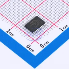
PIC 16 Bit 32MHz TQFP-100(12x12) Microcontrollers RoHS

TQFP-100(12x12)ROHS3 CompliantActive

16-Bit eXtreme Low-Power Microcontrollers with LCD Controller and USB

Manufacturer
MICROCHIP
Manufacturer part #
PIC24FJ128GU410-I/PT
Store part #
C1015891
Package / case
TQFP-100(12x12)
Packaging
Tray
Datasheet (PDF)

Every Order Guarantee

100% Authentic · 30-Day Return or Replacement · policy

101 in stock

#C1015891

Stock & price checked 4 days ago

QuantityUnit pricePack price
1+₹840.44₹840.44
10+₹820.42₹8,204.20
30+₹806.86₹24,205.80
100+₹793.51₹79,351.00

1 × ₹840.44

₹840.44

excl. GST

₹991.72 incl. 18% GST

Need volume or a scheduled delivery? Request a quote
  • Dispatch in 15-18 working days
  • GST invoice with every order
  • Standard pack: 119 per tray

PIC24FJ128GU410-I/PT

₹840.44 for 1 + GST

Need this with the rest of your board? Upload the BOM — we price every line.Upload BOM

Specifications

DAC (Bit)
10bit
ADC (Bit)
10bit;12bit
Operating Temperature
-40℃~+85℃
Program Memory Type
FLASH
Voltage - Supply
2V~3.6V
Program Storage Size
128KB
CPU Core
PIC
Core Size
16 Bit
CPU Maximum Speed
32MHz
Oscillator Type
Built-in

Packaging & compliance

RoHS
ROHS3 Compliant
Lifecycle
Active
ECCN
3A991A2
Packaging
Tray
Standard pack
119 / Tray
Sold per
Piece
Minimum order
1
Unit weight
0.001 g

Overview

Key features

  • Modified Harvard Architecture
  • 512 Kbytes Flash Memory 32 Kbytes RAM Up to 16 MIPS Operation @ 32 MHz
  • 17-Bit x 17-Bit Single-Cycle Hardware Fractional/Integer Multiplier
  • 32-Bit by 16-Bit Hardware Divider
  • 16-Bit x 16-Bit Working Register Array C Compiler Optimized Instruction Set Architecture Two Address Generation Units for Separate Read and Write Addressing of Data Memory
  • 64 Segments and 8 Commons Supporting up to 480 Pixels
  • LCD Charge Pump with 5 μA Low Power Core-Independent LCD Animation Operation in Sleep Mode
  • Up to 24-Channel, Software Selectable 10/12-Bit Analog-to-Digital Converter:
  • 12-bit, 350K samples/second conversion rate (single Sample-and-Hold)
  • 10-bit, 400K samples/second conversion rate (single Sample-and-Hold)
  • Sleep mode operation
  • Low-voltage boost for input
  • Band gap reference input feature
  • Core-independent windowed threshold compare feature
  • Auto-scan feature
  • Three Analog Comparators with Input Multiplexing: Programmable reference voltage for comparators
  • 10-Bit, 1 Msps DAC with Buffered Output
  • Sleep and Idle modes Selectively Shut Down: Peripherals and/or core for substantial power reduction and fast wake-up
  • Doze mode Allows CPU to Run at a Lower Clock Speed than Peripherals
  • Alternate Clock modes Allow On-the-Fly: Switching to a lower clock speed for selective power reduction
  • Retention Sleep with On-Chip Ultra Low-Power Retention Regulator
  • Fail-Safe Clock Monitor Operation: Detects clock failure and switches to on-chip, low-power RC Oscillator
  • Power-on Reset (POR), Brown-out Reset (BOR) Power-up Timer (PWRT) and Oscillator Start-up Timer (OST)
  • Programmable High or Low-Voltage Detect (HLVD)
  • Flexible Watchdog Timer (WDT) with RC Oscillator for Reliable Operation
  • Deadman Timer (DMT) for Safety-Critical Applications
  • Programmable 32-Bit Cyclic Redundancy Check (CRC) Generator
  • Flash Configurable as OTP by ICSP Write Inhibit
  • CodeGuard Security ECC Flash Memory with Fault Injection: Single Error Correction (SEC) Double-Error Detection (DED)
  • Customer OTP Memory Unique Device Identifier (UDID), 120-Bit Unique ID
  • Supply Voltage Range of 2.0V to 3.6V
  • Operating Ambient Temperature Range of -40°C to +125°C
  • On-Chip Voltage Regulators (1.8V) for Low-Power Operation
  • Large, Dual Partition Flash Program Array:
  • The device’s Flash memory can be configured into two physical sections or a single physical section
  • Capable of holding two independent software applications, including bootloader
  • Permits simultaneous programming of one partition while executing application code from the other
  • Allows run-time switching between Active Partitions
  • Flash Memory: 10,000 erase/write cycle endurance, typical Data retention: 20 years minimum
  • Self-programmable under software control
  • Flash OTP emulation
  • 8 MHz Fast RC Internal Oscillator: Multiple clock divide options Fast start-up
  • 96 MHz PLL Option
  • Programmable Reference Clock Output
  • In-Circuit Serial Programming (ICSP) and In-Circuit Emulation (ICE) via Two Pins
  • JTAG Boundary Scan Support
  • Independent, Low-Power 32 kHz Timer Oscillator
  • Six-Channel DMA Controller: Minimizes CPU overhead and increases data throughput
  • Timer1: 16-Bit Timer/Counter with External Crystal Oscillator; Timer1 can Provide an A/D Trigger
  • Timer2,3,4,5: 16-Bit Timer/Counter, can Create 32-Bit Timer; Timer3 and Timer5 can Provide an A/D Trigger
  • Eight MCCP modules, Each with a Dedicated 16/32-Bit Timer:
  • Three 6-output MCCP modules
  • Five 2-output MCCP modules
  • Four Variable Widths, Serial Peripheral Interface (SPI) Ports on All Devices; Three Operation modes:
  • Three-wire SPI (supports all four SPI modes)
  • Up to 32-byte deep FIFO buffer
  • I2S mode
  • Speed up to 24 MHz
  • Three I²C Master and Slave w/Address Masking, PMBus and IPMI Support
  • Six UART modules:
  • LIN/J2602 bus support (auto-wake-up, Auto-Baud Detect, Break character support)
  • RS-232 and RS-485 support
  • IrDA mode (hardware encoder/decoder functions)
  • Five External Interrupt Pins
  • Hardware Real-Time Clock and Calendar (RTCC)
  • Peripheral Pin Select (PPS) allows Independent I/O Mapping of Many Peripherals
  • Configurable Interrupt-on-Change on All I/O Pins: Each pin is independently configurable for rising edge or falling edge change detection
  • Reference Clock Output with Programmable Divider
  • Four Configurable Logic Cell (CLC) Blocks:
  • Two inputs and one output, all mappable to peripherals or I/O pins
  • AND/OR/XOR logic and D/JK flip-flop functions

Same category

More in Microcontrollers

View all